The second phase was to connect a logic analyzer onto the main bus to reorganize the load/store GPU instructions to take account of the real read/write delay on the bus.


In 2008, Orion_ made a Planar to Chunky in GPU to convert ST bit plan pictures to Jaguar compatible format.
In the next photos, you will see the result of the test program that display a simple st picture 320 x 200 x 4bit. The White background is the time taken by the GPU code to convert the picture from planar to chunky.

We can see that the conversion takes almost all the screen, and make it unusable to use for realtime applications.

Hmm, ok, there is a lot of difference between VJ and the reality.

With this last optimized version, we gain enough POWA to use it in realtime.
Let's see how the code was optimized.
Original Source Code :
;******************************************
; ST to Jag GPU Routine - by Orion_ [2008]
;******************************************
; Convert a planar 4 planes ST screen to a chunky 4bits Jaguar screen


;abcdefghijklmnopqrstuvwxyzABCDEF
;GHIJKLMNOPQRSTUVWXYZ0123456789-+

;WGqaXHrbYIscZJtd0Kue1Lvf2Mwg3Nxh	<- r2
;4Oyi5Pzj6QAk7RBl8SCm9TDn-UEo+VFp	<- r5

;Table de valeurs 256 (long):
;   ------------------------abcdefgh
;-> ---a---b---c---d---e---f---g---h


InitST2JAG:
	movei	#ST2JAGTable,r0
	movei	#STGenloop,r11

	moveq	#0,r1
	movei	#256,r12

STGenloop:
	moveq	#1,r2
	move	r1,r3
	move	r1,r4
	move	r1,r5
	move	r1,r6
	move	r1,r7
	move	r1,r8
	move	r1,r9
	move	r1,r10
	and		r2,r3
	shlq	#1,r2
	and		r2,r4
	shlq	#1,r2
	shlq	#3,r4
	and		r2,r5
	shlq	#1,r2
	or		r4,r3
	shlq	#6,r5
	and		r2,r6
	shlq	#1,r2
	or		r5,r3
	shlq	#9,r6
	and		r2,r7
	shlq	#1,r2
	or		r6,r3
	shlq	#12,r7
	and		r2,r8
	shlq	#1,r2
	or		r7,r3
	shlq	#15,r8
	and		r2,r9
	shlq	#1,r2
	or		r8,r3
	shlq	#18,r9
	and		r2,r10
	shlq	#21,r10
	or		r9,r3
	addq	#1,r1
	or		r10,r3
	store	r3,(r0)
	subq	#1,r12
	jump	NE,(r11)
	addqt	#4,r0

	StopGPU

;--------------------------------

ConvertST2JAG:
	movei	#BG,r17
	movei	#$FFFF,r0
	storew	r0,(r17)

	movei	#STScreen,r10	; both long aligned
	movei	#next_screen,r15

	load	(r10),r10
	load	(r15),r15

	movei	#ST2JAGTable,r14
	movei	#255*4,r8
	movei	#STloop16,r9
	movei	#(320*200)/(8*2),r11
	movei	#G_HIDATA,r16

STloop16:
	loadp	(r10),r4
	addq	#8,r10

	move	r4,r5
	load	(r16),r0
	move	r4,r5
	move	r4,r6
	move	r4,r7
	move	r0,r1
	move	r0,r2
	move	r0,r3

	shrq	#24-2,r0
	shrq	#16-2,r1
	shrq	#8-2,r2
	shlq	#2,r3
	shrq	#24-2,r4
	shrq	#16-2,r5
	shrq	#8-2,r6
	shlq	#2,r7

	and		r8,r0
	and		r8,r1
	and		r8,r2
	and		r8,r3
	and		r8,r4
	and		r8,r5
	and		r8,r6
	and		r8,r7

	load	(r14+r0),r0	; abcdefgh
	load	(r14+r1),r1	; ijklmnop
	load	(r14+r2),r2	; qrstuvwx
	load	(r14+r3),r3	; yzABCDEF
	load	(r14+r4),r4	; GHIJKLMN
	load	(r14+r5),r5	; OPQRSTUV
	load	(r14+r6),r6	; WXYZ0123
	load	(r14+r7),r7	; 456789-+

	rorq	#31,r2
	rorq	#31,r3
	rorq	#30,r4
	rorq	#30,r5
	rorq	#29,r6
	rorq	#29,r7

	or		r2,r0
	or		r3,r1
	or		r4,r0
	or		r5,r1
	or		r6,r0
	or		r7,r1

	store	r0,(r16)
	storep	r1,(r15)	; store 16 colors

	subq	#1,r11
	jump	NE,(r9)
	addqt	#8,r15

	storew	r11,(r17)

	StopGPU

;--------------------------------

	.long
STScreen:	dc.l	0		; Screen Pointer MUST BE LONG ALIGNED !!!!
ST2JAGTable:	dcb.l	256,0		; Precalc Table 1Kbytes
The function "InitST2JAG" create a precompute table that is stocked in the GPU internal ram that expend a "------------------------abcdefgh" pattern to "---a---b---c---d---e---f---g---h".
Then the "ConvertST2JAG" read a phrase and explode it to 4x 8-bit pattern and use the precalc table to expend it to chunky data.
Each 4 result are then combined to form the final chunky data and we write back a phrase to the framebuffer.
The first function doesn't need to be optimized since it is launch only one time, but we will do it for learning purpose.
First, we will count the Cycle needed to execute the loop, by taking account all GPU RISC limitations :
STGenloop:
    moveq   #1,r2           ;   #1              |   -           |   -
    move    r1,r3           ;   Rr1             |   -           |   Wr2
    move    r1,r4           ;   Rr1             |   -           |   Wr3
    move    r1,r5           ;   Rr1             |   -           |   Wr4
    move    r1,r6           ;   Rr1             |   -           |   Wr5
    move    r1,r7           ;   Rr1             |   -           |   Wr6
    move    r1,r8           ;   Rr1             |   -           |   Wr7
    move    r1,r9           ;   Rr1             |   -           |   Wr8
    move    r1,r10          ;   Rr1             |   -           |   Wr9
                            ;   -               |   -           |   Wr10
    and     r2,r3           ;   Rr2     Rr3     |   -           |   -
    shlq    #1,r2           ;   #1      Rr2     |   Cr3         |   -
                            ;   -               |   Cr2         |   Wr3
    and     r2,r4           ;   Rr2     Rr4     |   -           |   Wr2
    shlq    #1,r2           ;   #1      Rr2     |   Cr4         |   -
    shlq    #3,r4           ;   #3      Rr4     |   Cr2         |   Wr4
    and     r2,r5           ;   Rr2     Rr5     |   Cr4         |   Wr2
    shlq    #1,r2           ;   #1      Rr2     |   Cr5         |   Wr4
                            ;   -               |   Cr2         |   Wr5
                            ;   -               |   -           |   Wr2
    or      r4,r3           ;   Rr4     Rr3     |   -           |   -
    shlq    #6,r5           ;   #6      Rr5     |   Cr3         |   -
                            ;   -               |   Cr5         |   Wr3
                            ;   -               |   -           |   Wr5
    and     r2,r6           ;   Rr2     Rr6     |   -           |   -
    shlq    #1,r2           ;   #1      Rr2     |   Cr6         |   -
                            ;   -               |   Cr2         |   Wr6
                            ;   -               |   -           |   Wr2
    or      r5,r3           ;   Rr5     Rr3     |   -           |   -
    shlq    #9,r6           ;   #9      Rr6     |   Cr3         |   -
                            ;   -               |   Cr6         |   Wr3
                            ;   -               |   -           |   Wr6
    and     r2,r7           ;   Rr2     Rr7     |   -           |   -
    shlq    #1,r2           ;   #1      Rr2     |   Cr7         |   -
                            ;   -               |   Cr2         |   Wr7
                            ;   -               |   -           |   Wr2
    or      r6,r3           ;   Rr6     Rr3     |   -           |   -
    shlq    #12,r7          ;   #12     Rr7     |   Cr3         |   -
                            ;   -               |   Cr7         |   Wr3
                            ;   -               |   -           |   Wr7
    and     r2,r8           ;   Rr2     Rr8     |   -           |   -
    shlq    #1,r2           ;   #1      Rr2     |   Cr8         |   -
                            ;   -               |   Cr2         |   Wr8
                            ;   -               |   -           |   Wr2
    or      r7,r3           ;   Rr7     Rr3     |   -           |   -
    shlq    #15,r8          ;   #15     Rr8     |   Cr3         |   -
                            ;   -               |   Cr8         |   Wr3
                            ;   -               |   -           |   Wr8
    and     r2,r9           ;   Rr2     Rr9     |   -           |   -
    shlq    #1,r2           ;   #1      Rr2     |   Cr9         |   -
                            ;   -               |   Cr2         |   Wr9
                            ;   -               |   -           |   Wr2
    or      r8,r3           ;   Rr8     Rr3     |   -           |   -
    shlq    #18,r9          ;   #18     Rr9     |   Cr3         |   -
                            ;   -               |   Cr9         |   Wr3
                            ;   -               |   -           |   Wr9
    and     r2,r10          ;   Rr2     Rr10    |   -           |   -
                            ;   -               |   Cr10        |   -
    shlq    #21,r10         ;   #21     Rr10    |   -           |   Wr10
    or      r9,r3           ;   Rr9     Rr3     |   Cr10        |   -
    addq    #1,r1           ;   #1      Rr1     |   Cr3         |   Wr10
    or      r10,r3          ;   Rr10    Rr3     |   Cr1         |   Wr3
                            ;   -               |   Cr3         |   Wr1
    store   r3,(r0)         ;   Rr3     Rr0     |   -           |   Wr3
    subq    #1,r12          ;   #1      Rr12    |   -           |   -
                            ;   -               |   Cflags      |   -
    jump    NE,(r11)        ;   NE+Rflags Rr11  |   -           |   Wflags
    addqt   #4,r0           ;   #4      Rr0     |   -           |   -
                            ;   -               |   Cr0         |   -
                            ;   -               |   -           |   Wr0
We can see that one loop will take 70 cycles, and has 43 useful cycles, that makes only 61% use of the GPU POWA.
Then, after reordering all instructions to take advantage of the pipeline, the result is :
STGenloop:
	moveq	#1,r2			;	#1				|	-			|	-
	move	r1,r4			;	Rr1				|	-			|	Wr2
	move	r1,r5			;	Rr1				|	-			|	Wr4
	move	r1,r6			;	Rr1				|	-			|	Wr5
	move	r1,r7			;	Rr1				|	-			|	Wr6
	move	r1,r8			;	Rr1				|	-			|	Wr7
	move	r1,r9			;	Rr1				|	-			|	Wr8
	move	r1,r10			;	Rr1				|	-			|	Wr9
	move	r1,r3			;	Rr1				|	-			|	Wr10
	and		r2,r3			;	Rr2		Rr3		|	-			|	Wr3
	shlq	#1,r2			;	#1		Rr2		|	Cr3			|	-
	nop						;	-				|	Cr2			|	Wr3
	and		r2,r4			;	Rr2		Rr4		|	-			|	Wr2
	shlq	#1,r2			;	#1		Rr2		|	Cr4			|	-
	shlq	#3,r4			;	#3		Rr4		|	Cr2			|	Wr4
	and		r2,r5			;	Rr2		Rr5		|	Cr4			|	Wr2
	or		r4,r3			;	Rr4		Rr3		|	Cr5			|	Wr4
	shlq	#6,r5			;	#6		Rr5		|	Cr3			|	Wr5
	shlq	#1,r2			;	#1		Rr2		|	Cr5			|	Wr3
	or		r5,r3			;	Rr5		Rr3		|	Cr2			|	Wr5
	and		r2,r6			;	Rr2		Rr6		|	Cr3			|	Wr2
	shlq	#1,r2			;	#1		Rr2		|	Cr6			|	Wr3
	shlq	#9,r6			;	#9		Rr6		|	Cr2			|	Wr6
	and		r2,r7			;	Rr2		Rr7		|	Cr6			|	Wr2
	or		r6,r3			;	Rr6		Rr3		|	Cr7			|	Wr6
	shlq	#1,r2			;	#1		Rr2		|	Cr3			|	Wr7
	shlq	#12,r7			;	#12		Rr7		|	Cr2			|	Wr3
	and		r2,r8			;	Rr2		Rr8		|	Cr7			|	Wr2
	or		r7,r3			;	Rr7		Rr3		|	Cr8			|	Wr7
	shlq	#1,r2			;	#1		Rr2		|	Cr3			|	Wr8
	shlq	#15,r8			;	#15		Rr8		|	Cr2			|	Wr3
	and		r2,r9			;	Rr2		Rr9		|	Cr8			|	Wr2
	or		r8,r3			;	Rr8		Rr3		|	Cr9			|	Wr8
	shlq	#1,r2			;	#1		Rr2		|	Cr3			|	Wr9
	shlq	#18,r9			;	#18		Rr9		|	Cr2			|	Wr3
	and		r2,r10			;	Rr2		Rr10	|	Cr9			|	Wr2
	or		r9,r3			;	Rr9		Rr3		|	Cr10		|	Wr9
	shlq	#21,r10			;	#21		Rr10	|	Cr3			|	Wr10
	addq	#1,r1			;	#1		Rr1		|	Cr10		|	Wr3
	or		r10,r3			;	Rr10	Rr3		|	Cr1			|	Wr10
	subq	#1,r12			;	#1		Rr12	|	Cr3			|	Wr1
	store	r3,(r0)			;	Rr3		Rr0		|	Cr12		|	Wr3
	jump	NE,(r11)		;	NE+Rflags Rr11	|	-			|	Wr12 +Wflags
	addqt	#4,r0			;	#4		Rr0		|	-			|	-
							;	-				|	Cr0			|	-
							;	-				|	-			|	Wr0
We can see that the loop takes now 46 cycles, and has 43 useful cycles, that makes 93% use of the GPU POWA with less cycles (46 instead of 70) for each loop.
OK, we have optimized the Init Loop (that was not needed since it's launch only one time, but it shows what we can do with proper optimization :)
Now, we will work on the ConvertST2JAG function.
First, we will count the Cycle needed to execute the loop, by taking account all GPU RISC limitations.
STloop16:
	loadp	(r10),r4		;	Rr10			|	-			|	-
	addq	#8,r10			;	#8 		Rr10	|	-		M	|	-
							;	-				|	Cr10	M	|	-
							;	-				|	-		M	|	Wr10
							;	-				|	-		M	|	-
							;	-				|	-		M	|	-
							;	-				|	-		M	|	-
							;	-				|	-		M	|	-
							;	-				|	-		M	|	-
							;	-				|	-		M	|	-
							;	-				|	-		M	|	-
							;	-				|	-		M	|	-
	move	r4,r5			;	Rr4				|	-			|	Wr4
	load	(r16),r0		;	Rr16			|	-			|	Wr5
							;	-				|	-		I	|	-
	move	r4,r5			;	Rr4				|	-			|	Wr0
	move	r4,r6			;	Rr4				|	-			|	Wr5
	move	r4,r7			;	Rr4				|	-			|	Wr6
	move	r0,r1			;	Rr0				|	-			|	Wr7
	move	r0,r2			;	Rr0				|	-			|	Wr1
	move	r0,r3			;	Rr0				|	-			|	Wr2
	shrq	#24-2,r0		;	#24-2	Rr0		|	-			|	Wr3
	shrq	#16-2,r1		;	#16-2	Rr1		|	Cr0			|	-
	shrq	#8-2,r2			;	#8-2	Rr2		|	Cr1			|	Wr0
	shlq	#2,r3			;	#2		Rr3		|	Cr2			|	Wr1
	shrq	#24-2,r4		;	#24-2	Rr4		|	Cr3			|	Wr2
	shrq	#16-2,r5		;	#16-2	Rr5		|	Cr4			|	Wr3
	shrq	#8-2,r6			;	#8-2	Rr6		|	Cr5			|	Wr4
	shlq	#2,r7			;	#2		Rr7		|	Cr6			|	Wr5
							;	-				|	Cr7			|	Wr6
							;	-				|	-			|	Wr7
	and		r8,r0			;	Rr8		Rr0		|	-			|	-
	and		r8,r1			;	Rr8		Rr1		|	Cr0			|	-
							;	-				|	Cr1			|	Wr0
							;	-				|	-			|	Wr1
	and		r8,r2			;	Rr8		Rr2		|	-			|	-
	and		r8,r3			;	Rr8		Rr3		|	Cr2			|	-
							;	-				|	Cr3			|	Wr2
							;	-				|	-			|	Wr3
	and		r8,r4			;	Rr8		Rr4		|	-			|	-
	and		r8,r5			;	Rr8		Rr5		|	Cr4			|	-
							;	-				|	Cr5			|	Wr4
							;	-				|	-			|	Wr5
	and		r8,r6			;	Rr8		Rr6		|	-			|	-
	and		r8,r7			;	Rr8		Rr7		|	Cr6			|	-
							;	-				|	Cr7			|	Wr6
							;	-				|	-			|	Wr7
	load	(r14+r0),r0		;	Rr14	Rr0		|	-			|	-		; explode abcdefgh
							;	-				|	Cr14+r0		|	-
	load	(r14+r1),r1		;	Rr14	Rr1		|	-		I	|	-		; ijklmnop
							;	-				|	Cr14+r1		|	Wr0
	load	(r14+r2),r2		;	Rr14	Rr2		|	-		I	|	-		; qrstuvwx
							;	-				|	Cr14+r2		|	Wr1
	load	(r14+r3),r3		;	Rr14	Rr3		|	-		I	|	-		; yzABCDEF
							;	-				|	Cr14+r3		|	Wr2
	load	(r14+r4),r4		;	Rr14	Rr4		|	-		I	|	-		; GHIJKLMN
							;	-				|	Cr14+r4		|	Wr3
	load	(r14+r5),r5		;	Rr14	Rr5		|	-		I	|	-		; OPQRSTUV
							;	-				|	Cr14+r5		|	Wr4
	load	(r14+r6),r6		;	Rr14	Rr6		|	-		I	|	-		; WXYZ0123
							;	-				|	Cr14+r6		|	Wr5
	load	(r14+r7),r7		;	Rr14	Rr7		|	-		I	|	-		; 456789-+
							;	-				|	Cr14+r7		|	Wr6
	rorq	#31,r2			;	#31		Rr2		|	-		I	|	-
	rorq	#31,r3			;	#31		Rr3		|	Cr2			|	Wr7
	rorq	#30,r4			;	#30		Rr4		|	Cr3			|	Wr2
	rorq	#30,r5			;	#30		Rr5		|	Cr4			|	Wr3
	rorq	#29,r6			;	#29		Rr6		|	Cr5			|	Wr4
	rorq	#29,r7			;	#29		Rr7		|	Cr6			|	Wr5
							;	-				|	Cr7			|	Wr6
							;	-				|	-			|	Wr7
	or		r2,r0			;	Rr2		Rr0		|	-			|	-
	or		r3,r1			;	Rr3		Rr1		|	Cr0			|	-
	or		r4,r0			;	Rr4		Rr0		|	Cr1			|	Wr0
	or		r5,r1			;	Rr5		Rr1		|	Cr0			|	Wr1
	or		r6,r0			;	Rr6		Rr0		|	Cr1			|	Wr0
	or		r7,r1			;	Rr7		Rr1		|	Cr0			|	Wr1
	store	r0,(r16)		;	Rr0		Rr16	|	Cr1			|	Wr0
	storep	r1,(r15)		;	Rr1		Rr15	|	-			|	Wr1		; store 16 colors
	subq	#1,r11			;	#1		Rr11	|	-			|	-
							;	-				|	Cr11		|	-
	jump	NE,(r9)			;	Rflags	Rr9		|	-			|	Wr11 + flags
	addqt	#8,r15			;	#8		Rr15	|	-			|	-
							;	-				|	Cr15		|	-
							;	-				|	-			|	Wr15
We can see that one loop will take 85 cycles, and has 51 useful cycles, that makes only 60% use of the GPU POWA.
This code is also highly cycle dependent from the main bus usage with the loadp instruction
We can make these modifications :
1) Extract the first loadp to have a prefetch data and avoid the ~10 dead cycles each loop from the main ram time access because we need immediately the memory data
2) Reordering all instructions to take account of the pipeline
More Extra optimisations :
1) Use of standard load instruction instead of the "load+Rn" instruction to allow more reordering and take full advantage of the pipeline
2) Remove some shifts instructions by using another precompute table that expand "----------------abcdefgh--------" pattern to "--a---b---c---d---e---f---g---h-".
This gives the next optimized result :
	loadp	(r10),r4		;	Rr10			|	-			|	-
	addq	#8,r10			;	#8 		Rr10	|	-		M	|	-
							;	-				|	Cr10	M	|	-
							;	-				|	-		M	|	Wr10
							;	-				|	-		M	|	-
							;	-				|	-		M	|	-
							;	-				|	-		M	|	-
							;	-				|	-		M	|	-
							;	-				|	-		M	|	-
							;	-				|	-		M	|	-
							;	-				|	-		M	|	-
							;	-				|	-		M	|	-
	move	r4,r5			;	Rr4				|	-			|	Wr4
	load	(r16),r0		;	Rr16			|	-			|	Wr5
STloop16:
	loadp	(r10),r24		;	Rr10			|	-			|	-
	move	r0,r1			;	Rr0				|	-			|	-
	move	r0,r2			;	Rr0				|	-			|	Wr1
	move	r0,r3			;	Rr0				|	-			|	Wr2
	move	r4,r6			;	Rr4				|	-			|	Wr3
	move	r4,r7			;	Rr4				|	-			|	Wr6
	shrq	#24-2,r0		;	#22		Rr0		|	-			|	Wr7
	shrq	#16-2,r1		;	#14		Rr1		|	Cr0			|	-
	and		r8,r0			;	Rr8		Rr0		|	Cr1			|	Wr0
	and		r8,r1			;	Rr8		Rr1		|	Cr0			|	Wr1
	add		r14, r0			;	Rr14	Rr0		|	Cr1			|	Wr0
	add		r14, r1			; 	Rr14	Rr1		|	Cr0			|	Wr1
	load	(r0), r0		;	Rr0				|	Cr1			|	Wr0		; abcdefgh
	load	(r1), r1		;	Rr1				|	Cr0		I	|	Wr1		; ijklmnop
	shrq	#8-2,r2			;	#6		Rr2		|	Cr1		I	|	Wr0
	shlq	#2,r3			;	#2		Rr3		|	Cr2			|	Wr1
	and		r8,r2			;	Rr8		Rr2		|	Cr3			|	Wr2
	and		r8,r3			;	Rr8		Rr3		|	Cr2			|	Wr3
	add		r18, r2			;	Rr14	Rr2		|	Cr3			|	Wr2
	add		r18, r3			;	Rr14	Rr3		|	Cr2			|	Wr3
	load	(r2), r2		;	Rr2				|	Cr3			|	Wr2		; qrstuvwx
	load	(r3), r3		;	Rr3				|	-		I	|	Wr3		; yzABCDEF
	shrq	#24-2,r4		;	#22		Rr4		|	-		I	|	Wr2
	shrq	#16-2,r5		;	#14		Rr5		|	Cr4			|	Wr3
	and		r8,r4			;	Rr8		Rr4		|	Cr5			|	Wr4
	and		r8,r5			;	Rr8		Rr5		|	Cr4			|	Wr5
	add		r14, r4			;	Rr14	Rr4		|	Cr5			|	Wr4
	add		r14, r5			;	Rr14	Rr5		|	Cr4			|	Wr5
	load	(r4), r4		;	Rr4				|	Cr5			|	Wr4		; GHIJKLMN
	load	(r5), r5		;	Rr5				|	-		I	|	Wr5		; OPQRSTUV
	shrq	#8-2,r6			;	#6		Rr6		|	-		I	|	Wr4
	shlq	#2,r7			;	#2		Rr7		|	Cr6			|	Wr5
	and		r8,r6			;	Rr8		Rr6		|	Cr7			|	Wr6
	and		r8,r7			;	Rr8		Rr7		|	Cr6			|	Wr7
	add		r18, r6			;	Rr14	Rr6		|	Cr7			|	Wr6
	add		r18, r7			;	Rr14	Rr7		|	Cr6			|	Wr7
	load	(r6), r6		;	Rr6				|	Cr7			|	Wr6		; WXYZ0123
	load	(r7), r7		;	Rr7				|	-		I	|	Wr7		; 456789-+
	or		r6, r4			;	Rr6		Rr4		|	-		I	|	Wr6
	or		r7, r5			;	Rr7		Rr5		|	Cr4			|	Wr7
	shlq	#2, r4			;	#2		Rr4		|	Cr5			|	Wr4
	shlq	#2, r5			;	#2		Rr5		|	Cr4			|	Wr5
	or		r4, r0			;	Rr4		Rr0		|	Cr5			|	Wr4
	or		r5, r1			;	Rr5		Rr1		|	Cr0			|	Wr5
	or		r2, r0			;	Rr2		Rr0		|	Cr1			|	Wr0
	or		r3, r1			;	Rr3		Rr1		|	Cr0			|	Wr1
	nop						;	-				|	Cr1			|	Wr0
	move	r24,r5			;	Rr24			|	-			|	Wr1
	move	r24,r4			;	Rr24			|	-			|	Wr5
	load	(r16),r20		;	Rr16			|	-			|	Wr4
	store	r0,(r16)		;	Rr0		Rr16	|	-		R	|	-
	subq	#1,r11			;	#1		Rr11	|	-			|	Wr20
	storep	r1,(r15)		;	Rr1		Rr15	|	Cr11		|	-		; store 16 colors
	move	r20,r0			;	Rr20			|	-			|	Wr11 +Wflags
	addqt	#8,r10			;	#8		Rr10	|	-			|	Wr0
	jump	NE,(r9)			;	NE+Rflags Rr9	|	Cr10		|	-
	addqt	#8,r15			;	#8		Rr15	|	-			|	Wr10
							;	-				|	Cr15		|	-
							;	-				|	-			|	Wr15
We can see that now, the first loop will take 73 cycles, and has 60 useful cycles, that makes 82% use of the GPU POWA.
All other loops will take 59 cycles with 56 useful cycles, that makes 95% use of the GPU POWA with less cycles (59 instead of 85) for each loop.
By using the pipeline and making a little algorithm modification, we reduce by 30% the time to made the planar to chunky.


The NyanCat for the Atari Jaguar
2014/12/13 => Updated : Some bugs with the JagFPGA have been removed.
This minidemo was made to answer to the NyanCatari. :)

Full ACTion Sprites (FACTS) is a demo written for the JagCode II contest.
This demo show what the Object Processor is capable of.
The first screen is composed of 4 spirales compute in real time by the GPU with the mathematic formula :
The second screen is composed of a picture cutted into 204/4 * 148/4 = 1887 objects of 4x4 16bpp.
The position of objects is computed in real time by the GPU with the mathematic formula :
The first optimization phase was made by using all register and taking acount of the GPU's RISC pipeline architecture.
The second phase was to connect a logic analyzer onto the main bus to reorganize the load/store GPU instructions to take account of the real read/write delay on the bus.
The Object list is organized to have up to 128 objects for 4 physical lines and there is 240/4= 60 list line. Theoricaly we can have 60*128 = 7680 Objects in the list each frame
In reality, the bandwidth of the main memory will not be enough to allow so many objects.
To take account of object that is not on 4 lines boundary, each time the OP start, it will read 2 consecutive packets of 128 objects. With this method we can reach 2500 objects each frame.
exemple :
The difficulty when we have so many sprites, is that the OP takes many bandwidth to the DRAM so we have not so many time to create the Object List.
For exemple, in NTSC, there is 25 blanking line and 244 visible line.
so if we push the OP to it's limit you can not access to the DRAM during 244 line and we have only 25 line to create the next list and all other things.
The next limitation is to do a OP list that don't take more than 63.55µs to reach the STOP object else there will be glitch on screen.
About technical choice on FACTS :
With a logic analyzer we can see that the object processor have a quicker data access for the 2 first phrase of bmp data (due to pipeline effect).
So I have the choice between 4x4 sprites and 8x8 sprites.
With 4 width sprites, the OP read the BMP header and the first line of the sprite in 14 cycles (@26.59MHz) so in 63.55µs we could have 63.55µs*26.59MHz/14 = 120 sprites per line. (and the RMW mode doesn't take more cycle with this sprite size \o/)
but create a list of 244 line of 120 sprites is impossible and 1 line by sprite is too difficult to manage.
It's more interesting to have square sprite
That's why I have cut the sprite list in 60 band of 4 lines (=244 visible line)
But like I said before, we can have 120 sprites per line so about 120 sprites into the band. (because the OP should have finished the band in 63.55µs)
The next thing to think about is the case of sprite that is between 2 band, and for that there is 2 solution :
- cut the sprite and add it to both band
or
- the OP read 2 band by line so it can finish to draw previous sprite.
I have chosen the 2nd one, because it's the one that take less CPU time.
Then to have the maximum bandwidth for the GPU and the OP we should limit the use of the DRAM by the DSP and the 68k, for that in the demo the 68k are stopped and the DSP don't use the DRAM to generate the sound (thanks to zerosquare ! \o/)
With so many sprite, we have no choice than to create 2 sprites list
And we need also many memory space
For the demo, the sprite list takes about 256kbytes of memory.
In the spirale part, the GPU compute about 2688 sprites coordinate but all these sprites are not visible (about 1900 are always visible and up to 2090 visible)
There is about 135 GPU cycle to add a sprite to the list. It's a very optimised code : {read sin/cos value, compute coordinate x/y, clipping x/y, compute bmp header, append the sprite to the list} for each sprites
To draw spirale and move it with this precision, there is a very accurate cos/sin table
All GPU code takes about 2kbytes and there is about 2kbytes of table for the glass effect and there is only 4 free bytes into the GPU memory !
I used also some tricks for the GPU code like automodifying code to reduce the size of the GPU code
Pour faire l'overclock il faut effectuer les opérations suivantes :
(à lire en entier avant de procéder)
(je ne peux pas faire mieux pour l'instant : je ne peux pas démonter facilement mes modifs pour pouvoir prendre des photos, j'ai pris ce que j'avais)
Je ne peux être tenu responsable des dégats si vous abimez votre console en tentant d'effectuer les modifications suivantes.
1ere partie : séparation des horloges Vidéo et Global
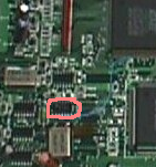
- couper la piste qui relis la clock 26.59MHz à VCLK de TOM
(en bleu : le point de test TP3, entouré en rouge : la piste à couper)

- souder un fils à wrapper entre la patte 66 de TOM (normalement il y a un point de test TP3 pas loin que l'on peut utiliser pour souder le fils) et la patte 1 ou 13 de U11 (ça va dépendre de la stabilité de la jag)
(en bleu : le point de test TP3 en haut à droite et la patte 1 de U11 en bas à gauche)

=> sur ma jag ces 2 premières modifs étaient d'origine (début de série américaine)
2eme partie : overclockage
le but est d'injecter une autre fréquence sur l'horloge Global
- le plus simple est de soulever la patte 13 de U11 ce qui isole le 26.59MHz du Global
(en saumon : U11)
- souder un fils à wrapper en utilisant le point de test TP25 ou les contacts non utilisés de L32 (qui sont court-circuités) qui va aller vers la nouvelle référence d'horloge (quartz, oscillateur, ou autre du moment que c'est un signal carré 50% )
(en jaune : L32)

remarques :
- les fils doivent être le plus court possible
- si on veut switcher entre les 2 fréquences, il faut ajouter de la logique.
testé a différentes fréquences : 32MHz, 37.5MHz, et 40MHz.
@ 32MHz ca marche impeccable
@ 37.5MHz on commence a sentir la limite du 68K, le cube de démarrage peux faire planter la console, néanmoins tous les jeux cartouches que j'ai (33 environ) fonctionnent une fois lancé.
@ 40MHz, ca plante completement.
Par contre, le son est acceleré.
voila de photos :
Premier tests

Montage final

petite demo sur FastLara de Orion_, la consommation en VBL correspond au rouge.
FastLara @ 32MHz
FastLara @ 37.5MHz
Zero5 @ 26.59MHz (frequence standard)
Zero5 @ 32MHz
Zero5 @ 37.5MHz
The jaguar PSU is 9V outside and GND inside :

To do this fix, you must have experience in SMT soldering. It's very important because components on the motherboard are very small and 2 components to change out of the 3 are SMT.
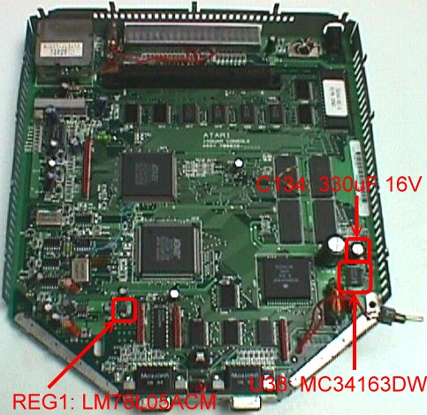
In my Jag, this component was blown.
You must remove this capacitor. Do not replace it before the next instruction : it will be easier to replace the next component.
This component is a power switching regulator (9V->5V 3A MAX) and it doesn't like it very much when the polarity is inverted. You can see heat damage on the surface of this component as shown below ( yours might not be bad as mine):

You shall replace it with the same part.
!!!!!!!!!!!!!!!!!!!!!!!!!!!!!!!!!!!!!!!!!!!!!!!!!!!!!!!!!!!!!!!!!!!!!!!!!!
!!!!!!!!!!!!!!WARNING : BE CARFUL WHEN YOU SOLDER SMTs!!!!!!!!!!!!!!!!!!!!!!
!!!!!!!!!!!!!!!!!!!!!!!!!!!!!!!!!!!!!!!!!!!!!!!!!!!!!!!!!!!!!!!!!!!!!!!!!!
If you don't find the MC34163DW you can use the MC33163DW, the difference is in the operating temperature range : the MC34163DW = 0 to 70°C and the MC33163DW = -40 to 85°C.
When you have replaced the U38, you can replace the C134.
This component is a DC/DC converter (9V->5V 100mA MAX) and it is used for the audio power.
As the U38, if it is dead, you can see heat damage on the surface as below :

If it is dead, you don't have sound when the Jag works.
You shall replace it with the same part.
Normally, if you replace these components with success, your Jag should work.
This video was originaly made to test the video digitizer of my ATI All in Wonder with my NTSC Jaguar. So I haven't play seriously to this great Game for this video ;)